|

|
|
 |
The Rechargeable
Battery "Cycler"
|
|
By:
Bertrand Zauhar, VE2ZAZ
Published
in the September/October
2008 issue of
ARRL's QEX Magazine
|
|
|
Page last
updated: 28/12/2008

|
|
This
page complements article
"The "Rechargeable Battery Cycler" published in
the September/October
2008
issue of ARRL's
QEX
magazine. This page also
provides
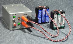
updates to the original article.
The
Battery Cycler is an autonomous device that
will
periodically discharge and
recharge Nickel Cadmium (Ni-Cd) or
Nickel-Metal-Hydride (Ni-MH) battery
packs
so that they are always fresh and ready to
deliver.
Please
visit
this
page
frequently, and right before assembling the
project, as new
information
may get added regularly.
Once again, I
would like to express my
gratitude to Jocelyne, my wife.This project took
6+ months of spare
time to develop, so she
deserves it! Also, thanks Jacques-VE2AZX for
beta-testing this system.
Bert,
VE2ZAZ
ORIGINAL
QEX MAGAZINE ARTICLE
|
For those
who have not read
the article
yet, this is the best place to start
learning about this project.
Reprinted with permission. Copyright ARRL,
2008 all rights reserved.
This material originally appeared in QEX:
Forum for Communications
experimenters (www.arrl.org/qex).
|
|
THE LATEST
NEWS, ERRATA AND
IMPROVEMENTS
|
(Added
28/12/2008)
A version 2 of
the Cycler
Configuration Software is available for
download. This version
offers a fix for the battery current
display,
which overlapped the "mA" label.
(Added
05/11/2008)
The original
QEX article is now
available here in PDF.
(Added 26/08/2008)
The original QEX article will be
available here in PDF form at the end of
the month of October
2008.
For now, exclusivity is given to the printed
magazine.
(Added
26/08/2008)
The
LED
contour markings on the PCB are
inverted for D2 and D3 if
using the suggested bi-color LEDs (Digikey 160-1038-ND). See the Assembly
Instructions section below.
(Added
26/08/2008)
Hammond
Enclosure.
I want to warn you that the suggested Hammond
enclosure
may be too small to work
with for some of you
(hands full of thumbs?). My goal was to fit
everything into the smallest
possible enclosure. If you are unsure about your
ability to fit
everything into the suggested enclosure, just
pick a bigger one. The Digikey website catalog
shows a list off all the
similar aluminum enclosures you can pick one from.
Just make sure you
select a box that has all its dimensions greater
or equal to the one I
am
suggesting.
I
appreciate reading
back from
experimenters who build this project. This allows
me to
improve this page by providing additional
clarification if necessary.
Thanks!
Due
to space constaints, the top-down view
of the PCB layout was not
published
in the QEX article. Here it is for
reference purpose.
Click on the figure to view it in
larger size ->
|

|
CONFIGURATION
SOFTWARE (WINDOWS)
|
This is the
Windows program that provides a user-friendly
interface to the Battery
Cycler system to configure it. The software
provides the
following
features:
- Microsoft
Windows-based
program with single window and tabs,
- All
parameters are set up and saved from
within one program,
- Serial
port driven; supports COM1 to COM8,
- Help
provided
via mouse
cursor hints,
- Only
required
at
configuration time or whenever log
monitoring is desired.
- Un-install
program
provided.
|
|
This
software
was developed and tested in a Windows 2000
environment. It was also
tested in Windows XP. Previous programs that
use the same COM port
driver were also successfully used on Windows
98. Since these operating
systems
cover two
main branches of Windows (9x and NT), the
software is expected to run
in all Windows environments from Windows 95
through Windows Vista.
Version History
Version
2
(December 2008)
This version
offers a fix for the battery current
display,
which overlapped the "mA" label on the
initial version.
Version 1
(August 2008)
Initial
release.
LEARNING
ABOUT AND
PROGRAMMING THE PIC FIRMWARE
|
If
you would like to look at the firmware
load running inside the PIC
micro-controller, well here it is! The
ASM
file is a text file of the source code
I wrote. Beware! This is
Assembly language...The code is well
documented though. Have fun... ;-)
I also provide the latest HEX file
required to upload the
firmware
load into the PIC 18F1220's program
flash. This file is in 8-bit Intel
HEX format, which is the industry
standard for 8-bit micro-controllers.
Note
that 5V
In-Circuit Serial Programming (ICSP)
is not supported on this firmware
load. All pins are assigned
to external functions, so the low
voltage ICSP programming
pins could not be spared for that
task. In order to
accomplish the firmware upload,
you need a PIC programmer
that can handle the PIC 18F series
chips and standard high-voltage
programming.
|
|
ADDITIONAL
ASSEMBLY
/ WIRING
INSTRUCTIONS
|
- The
TO-220 components (MOSFETS and Power
Resisor) can be mounted below
the PCB as shown on the figure to the
right. Alternatively, they can be
mounted above the PCB as long as they
make contact to one of the
enclosure walls for heat dissipation
purpose.
- The
MOSFETS must
be mounted with their
metal tab (case) "floating". This
calls for an an insulation kit for
both. Before powering up the Cycler, a
final check should be made with
an ohmmeter to ensure that the 2 metal
tabs are truly floating (high
resistance) from the metal enclosure.
Resistor R1 does not require
electrical insulation since there is
no metal on its case. A heat
conducting pad or some heat sink
compound is required though.
- The LED
contour markings on the PCB
are inverted for D2 and D3 if using
the suggested bi-color LEDs
(Digikey 160-1038-ND). See
the figure to the right on
how the LEDs should be mounted. The
red contours should match the LED
shapes.
- RS-232.
The RS-232 connection is a
simple 3-wire communication. No
handshaking
or strapping is required at the PC's
end. As well, you do not need to
set any COM port parameters within
Windows; the software sets these
when data exchange occurs.
|

Recommended
TO-220
components installation
Click
on
the
figure above to view them in larger
size.

D2, D3,
D6
LED orientation when using Digikey 160-1038-ND
Click on
the
figure above to view them in
larger size.
|
ADDITIONAL
OPERATING
INSTRUCTIONS
|
|