My 3.2m EME dish
project Par/by:
Bertrand
Zauhar,
VE2ZAZ
last updated :
March 2021
INTRODUCTION
Please note that this antenna setup no longer exists; it was disassembled in 2014.
For this project, I
rely a lot on the experience of others with dish antennas. What they
share on the web is very valuable. So I thought I would do the same to
help others the same way.
Owning a large parabolic dish
antenna
has always been the ultimate goal for me. EME (moonbounce) has given
me the excuse to proceed! Besides, two years of EME on 432 MHz has made
me realize that my QRP setup would not allow me to work tons of
stations. I work more or less the same stations in rotation. And I am
not willing to grow my 4 x 4.3 wavelength yagi array for several
practical reasons. The other consideration is that there are many more
stations on 1.2GHz EME than on 432MHz. And I need a new project to work
on!
A 10.5-foot (3.2 m) dish will provide a better performance on
1296 MHz (10+dB sun noise vs. 6dB with my 432 array) and an even better
performance on 2304 MHz.
I will spare you the details about negotiation with my wife, the
swimming pool, neighbors and so on. The bottom line is that thing are
progressing faster than expected!
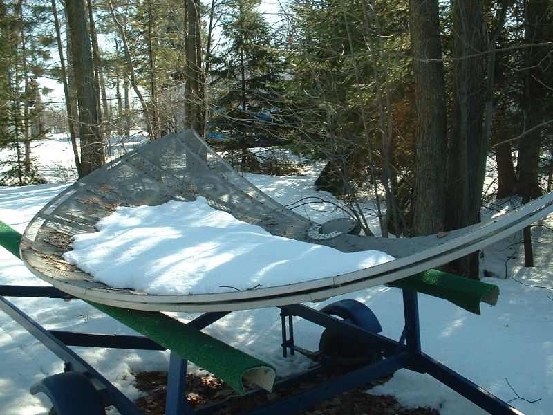
Fall 2008 My friend Robert - VE2ASL calls me up to
inform me that he spotted a 3.2 m all-aluminum TVRO mesh dish. It lies
on
the ground in good shape and is available for 50$. It is the dish only,
no hardware, no mount, no feed; just the dish. I say yes! This marks
the
beginning of my adventure...
So my friend brought it
back to his placeon a boat trailer during the winter season.
My first contact with the dish was through this picture to the right.
It would have to do for now...
This
project was supposed to be a long term one. I had agreed with my wife
to wait until our old above-ground swimming pool wears out beyond
repair before
installing the dish. This could be a few years...
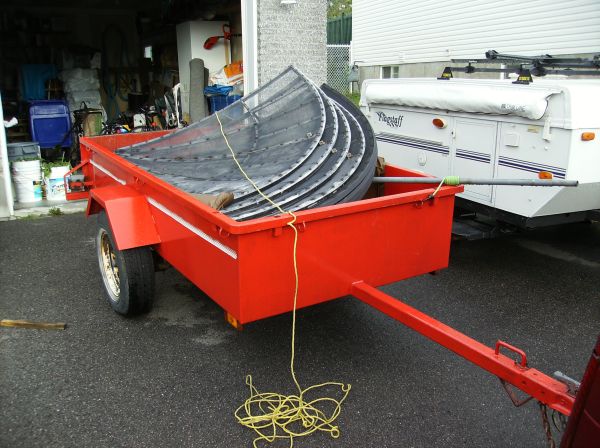
Summer
2009
I take possession of the dish and bring it home on our camping pop-up
trailer. The dish mesh is in pretty good shape. The
screws that hold the mesh in place are rusted though. I contemplate
replacing them with stainless steel hardware.
On another
front, I have the opportunity to purchase two more TVRO
dishes! They are a 2.7 m dish and a 3 m dish, both complete with all
the hardware, the actuators, the feeds and mounts. Even the receivers
and the cabling come with it... 75$ take them home. I don't really need
the dishes,
but I can certainly use the mounts and the actuators! Now I have what I
need to get going, at least I have a polar mount I can adapt for EME
use and a linear actuator to steer the dish.
Upon inspection, I notice that one of the linear actuators took water.
I completely disassemble it dry it out and lubricate the gears and
motor. In the end, it was a good learning exercise to understand how it
is built and controlled.
September
2009
The multi year wait is turning into an active
project. It occurs that there is a housing development just getting
going right behind our backyard fence. So with my wife's approval, I
decide to quickly erect one of the dishes (non-functional for now) as a
way to "mark my territory". The chosen location for the dish is not
ideal for west-pointing EME, but this is a temporary location (for a
few years, until the swimming pool disappears).
One critical decision before I start is to select the type of moon
tracking to implement. I elected to use polar tracking for my EME
operation. Implementing
a
Azimuth/Elevation
mount
requires heavy duty sprockets, chains, motors,
bearings and lots of welding. Since I am an illiterate in welding, this choice will save
me a lot of pain and money in the future. Besides, the ice and snow
here in Canada complicate everything even more if 12-month operation is
desired. Polar tracking will be much easier to implement, but will have
limitations and will require manual interventions, like changing the
actuator position to cover more of the moonrise or the moonset. I am
willing to deal with this for now.
The first step is to get a pipe to mount the dish on. A quick visit to
a recycling yard yields a 10 foot (3 m), 2 3/8 inch (6 cm) OD, thick
wall steel pipe. This is not as big of a pipe as I would have liked,
but it will work in my environment (houses that break the wind, not
living in a windy area). So I dig a 42 inch (1.1 m) deep, 15 x 15 inch (38 x 38
cm) square hole, a long and painful job since we live in on rocky land.
I then pour 8 cubic feet of concrete and also fill the pipe with the
mix.
After a week to
let the concrete set, I install one of the 10 foot (3 m) dishes with
the un-modified mount and without feedpoint or actuator. This is not
the dish that I will be using for EME; it is merely a placeholder. I
will work on the real dish this upcoming winter.
After
installation, I noticed that the pipe bends a little bit from vertical
due to the dish weight. It is not much for now, but once a feed is
installed, it will become more significant. I may decide to add a
counter-weight or guy wires. I will adapt when I get there.
November
2009
My
decision
to
install
a temporary dish to "mark my territory" was a good
one. Two houses are currently under construction behind my backyard
fence! Close call...
I
have completed the
replacement of the 500 rusted screws that hold the dish mesh in place.
I
have stainless steel screws in place now. Oh what a job! Regular steel
and aluminum do not get along well... It took me about 5 hours of work
divided down into ten half-hour sessions to complete the job.
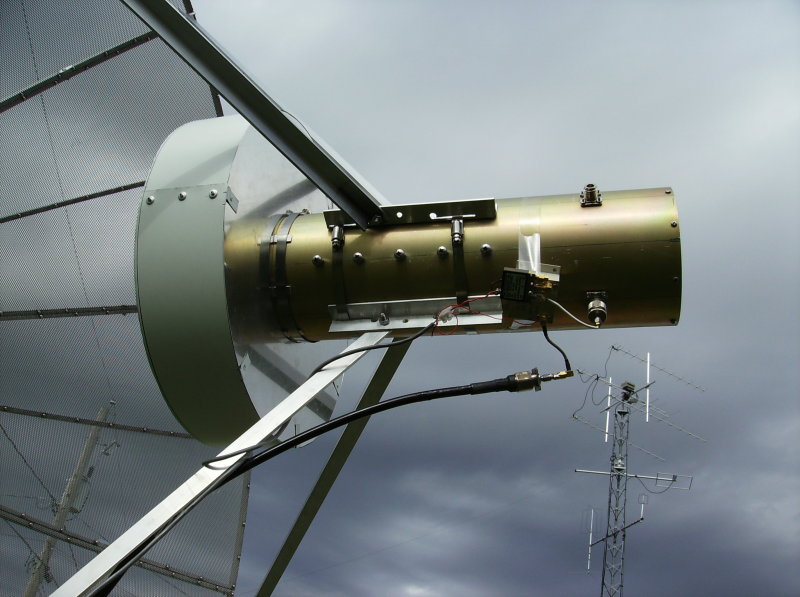
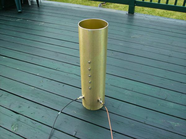
I
have also started to put
together the VE4MA feed. For the cylinder cavity, I used a Tx-Rx
Systems VHF duplexer cavity. Cheap and rugged (0.100 inch wall!). I cut
off the welded top end cap; that yielded a nice 6.4-inch diameter,
24-inch
long cylinder. I kept the removable bottom end cap, but added more
screws to fasten it.
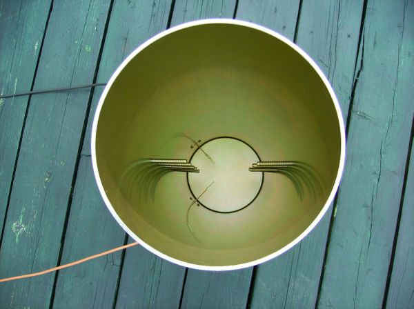
I drilled the N connectors and polarization screw holes as per VE4MA's drawings.
Note that, as
recommended by VE4MA himself, I
did not implement the nulling post. It apparently provides little
improvement in TX-RX port isolation. The result is what you see on the
right hand side pictures.
The initial testing of the feed without scalar ring and pointing to the
zenith gives promising results, with better than -20dB of return loss
on both port at 1336MHz. Port isolation is better than 28 dB. The peak
performance should normally show up at 1296MHz though, so there will be
a need for some tweaking. Axial
ratio (circularity) will be measured later.
The
list of things still to do is long:
Build a PHEMT LNA
Build a 200-300W Power Amplifier
Design changes to the polar mount
Design and construct the feedpoint arms
Design the Actuator controller
...
August
2010
A lot of things have happened in the last 10
months! Here is a summary:
Once again,
what a
good idea to put up a placeholder dish ASAP last fall. Now all the lots
behind my property are occupied by fully-constructed houses! I have
heard of no complaints as of today from any of my neighbors. One of
them actually offered to help out on the dish installation!
I first built an ATF54143 PHEMT LNA
(Preamp). The results are 18dB of gain and a Noise Figure of less than 0.3 dB. This will be a good
preamp for EME!
I
have performed more tests on the dish feed. The results are the same: I
am having problems bringing the resonance down from 1336MHz to 1296MHZ. I have lengthened the
probes and I have built a scalar ring made of cardboard and aluminum
but without success. Extending the cylinder length forward with
aluminum foil seem to improve the S11. This behavior is unexpected. I
will be spending more time on it once the hardware/mechanical on the
dish is
completed.
I
have found the type of tracking scheme I will be using to follow the
moon. It is called Azimuth-over-Elevation (as opposed to the classical
Elevation-over-Azimuth). Because my mount can easily tilt an
almost-full 90 degrees in elevation, this becomes the easiest way to do
tracking without any modification. The conversion of the Az-El data
from a tracking program to Az-over-El involves a few trigonometric
formulas. This is now understood and documented here.
The toughest math part is to figure out the current dish position as a
function of the actuator lengths. This required some serious kitchen
table trigonometry work... I think I have what I need and will be
putting it to the test soon...
The
Az-El moon data will be provided by Nova
for
Windows - a wonderful tracking program - using the Windows Dynamic Data
Exchange channel, which is supported by the software. Thanks to the
author, Michael Owen, for documenting the DDE feature for third-party
usage. It is very easy for any Windows program writer to use this
feature.
The
control of the antenna actuators will be performed as shown in the
figure below. This involves creating a Windows software that interprets
the Nova data, the actuators pulse counts and that steers the antenna
accordingly. The remote controller is located outdoors. It controls the
power relays to the actuator motors and it reads the pulse counts as
the actuators move. Both pieces are linked by a serial port link at
2400 bps. That link can be several hundred feet and will still work
fine, as tested on the At
Last
T/R Sequencer.
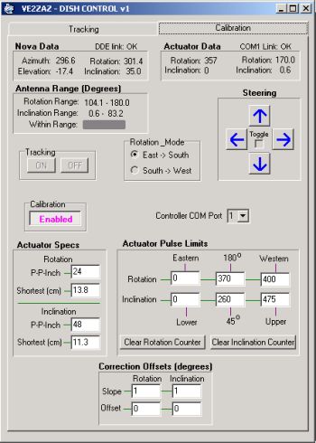
I
completed a first version of the Custom Windows software (see picture).
The
calibration process is also supported in the software. I used Delphi
(Object-oriented Visual Pascal) to accomplish this. I am currently
struggling with divide-by-zero and square root of negative value
errors. My calculations have to be accurate and robust!
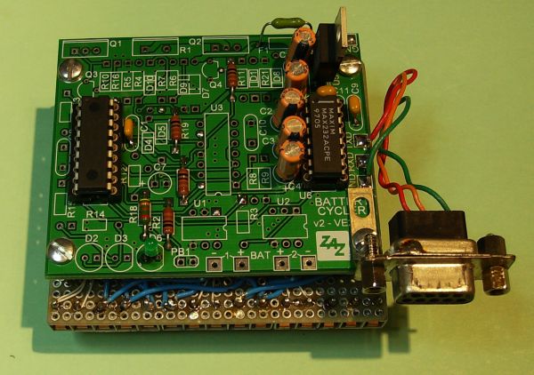
I
built and tested the remote controller (see pictures). I wrote the
firmware code in
assembly language. It runs on a PIC18F1220 micro-controller. A lot of
code re-use from my other projects was done. As physical support for
this controller, I used a "Rechargeable Battery Cycler"
PCB. This provided the voltage regulation, RS-232-to-TTL conversion and
PIC micro support, all "pre-wired" on a small PCB. When wiring the
power relays, I used a scheme that flips the actuator motor wires for
direction selection and that interlocks CW-CCW and Up-Down directions
respectively, i.e. opposite directions cannot be invoked
simultaneously, thanks to DPDT relays.
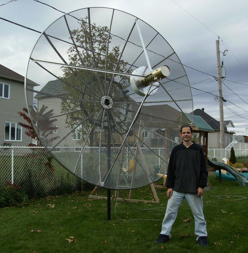
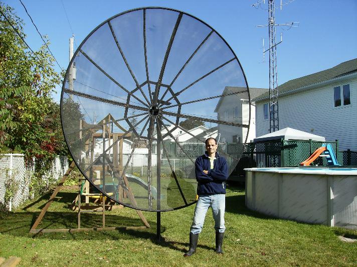
I
replaced the black 3.0m placeholder dish with the final 3.2m mesh dish.
The feedpoint arm brackets are installed and the arms are ready to be
installed and are ready to receive the feed. I even power-washed the
dish so that it shines in the sun... My wife is convinced that the
natural aluminum color shows less than the black. If she's happy with
this, then I'm happy!
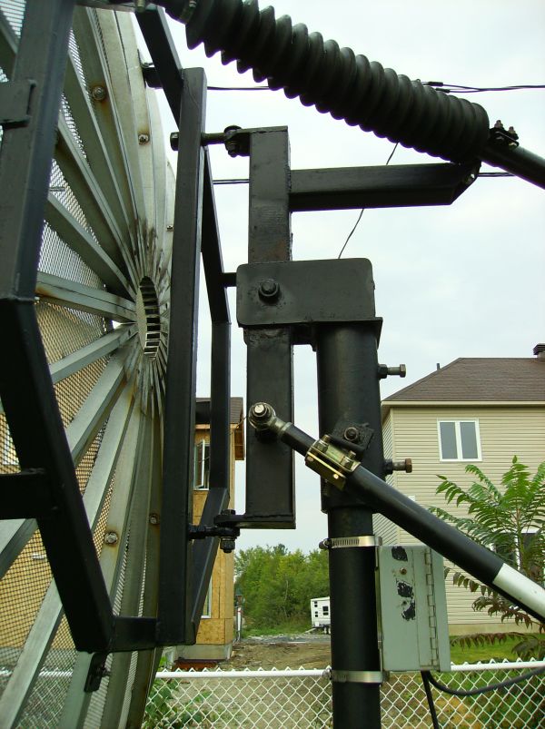
I
also installed and tested the two actuators (see picture). Cool to see
the dish move!
The Inclination actuator (18 inches long) provides a 0 to 85 degree
range. The Rotation actuator (24 inches long) provides a 100 to 190
degree azimuth range (with the mount oriented due-south). This is not
as much as I would have liked. When looking at the rotation actuator in
fully deployed position, there is still a lot of westward movement that
could be achieved with a longer actuator. This may or may not be
important since Pacific Ocean coverage is useless, and I would not
reach Asia or Australia anyway without transferring the actuator to the
other side of the dish. I also have the ability to turn the mount on
its post to adjust the range for better coverage of a point of
interest. All I have to do is take this into account in the Windows
software. This is likely a better avenue. I can see two positions of
the mount that would give me all the coverage that I need.
Hmmm....well, well.
The
list
of
things still left to do:
Make the Windows software bullet-proof,
Prove the math by checking for correct
orientation using the
sun,
Build a 200-300W Power Amplifier (a winter
project),
I have been bugged by actuator motor EMI/RFI
noise problems. Essentially, the pulse counting circuit gets triggered
by DC motor brushes noise. It flows all over the place on the
controller board! I am wasting precious time on this issue. I sent an
email on Moon-Net crying for help and got lots of good suggestions to
reduce that noise. Obviously, the noise should be reduced as close as
possible to the source, so at the motor end. RF choke and capacitive
decoupling is recommended. I tried a common-mode choke connected at the
motor terminal screws and it reduces the noise significantly.
Hopefully, this will be sufficient, along with running a separate shielded cable
for the reed pulse switch signals.
Despite the noise problem, I have been able to see that all the math
formulas to derive the rotation and inclination angles from the pulse
counts do work. A few evenings under the bright moon were enough to
prove this using the shadow generated by the feed arms. Some more work
is required to null out any offset or non-linearity. Objective is to be
within one degree of target.
I still don't have the cabling run between the shack and the
antenna, so every time I want to experiment, I need to bring computer,
power supply, controller board, necessary cabling, etc outdoors and
connect to the actuators. It represents a lot of handling, but to be
honest, I am not comfortable yet working remotely. I want to see, hear
and feel what is happening with the dish. One thing I will probably do
soon is wire up everything permanently, but bring out a netbook PC and
have a VNC remote session running to control the shack desktop PC.
On another front, it looks like I have covered enough exceptions in the
math formulas to make the Windows software work reliably. This is not
my main concern at this point though; the outdoors work is prioritized.
Finally, I have built and installed the super-scalar ring on the feed.
I am currently testing up the feed for VSWR, isolation and axial ratio.
More on this next time!
First-Half
of October 2010
We have liftoff!
I receive sun noise. During the last month I did a lot of work:
I
definitely solved
the actuator DC motor EMI noise by installing a common-mode choke on
the motor leads inside the actuator covers. The "Pulse P0502" toroid
choke is available from Digikey for around $5 US. A well-worth
investment! I also ran the pulse signal wires in a separate cable. Now
I don't mis-count pulses anymore. Problem solved!
I
managed to tune the feed for good reflection loss (23dB) and I also
adjusted the axial ratio to around 1dB. One important note when trying
to adjust for axial ratio: Rotate the feed, not the reference antenna.
Otherwise reflections will fool everything. I suspended the reference
antenna 3.5m above ground and used an office chair to rotate the feed
(pointing upward) under the reference antenna. Worked like a charm.
I ran the control and RF cables to the
shack. I installed the controller in a weather-tight box on the dish
post.
I installed the feed on the dish and
positioned it so that the focal point ends up inside the feed by 1-2 cm.
I
hooked up everything on the Rx port (SPDT relay and preamp) and ran
inside to make sun noise
measurements. The first results were 8.3dB of Sun-to-Cold_Sky noise.
This is around 2dB less than what was expected using VK3UM's EME
calculator program. I varied the feed distance from the dish but could
not improve. After discussing with Barry-VE4MA, it appears that
the 17.5dB of gain on the LNA (preamp) is insufficient when considering
the feedline losses and the receiver noise figure. A quick check with VK3UM's
EME calculator program (Receiver performance tab) confirmed this. I
need at least 30dB of gain in order to "stabilize" receiver
performance and get the full dynamic range. So I will build a second
ATF54143 LNA to put in cascade with the first one. At least I know the
recipe...
Second-Half
of October 2010
I managed to run a 70 feet-long Heliax 7/8"
from the dish to the shack.
This is the Tx line. The Rx line is heliax 1/2". Weatherizing of the
feedpoint will be temporary but that will suffice for this
winter. Let
it snow!
I found out that using the TS-2000X audio fed into the PC
sound card is not the good
way of measuring the sun noise. The radio (likely the I.F. DSP
stage) saturates and does not provide a linear audio output vs. RF
noise input, that is despite turning off the AGC! No wonder I was
measuring low in sun noise! I instead used a 1296-to-144MHz K7RR
downconverter, added two 144MHz preamps and a low-pass filter on the
transveter output and I fed this signal into a HP 70000-series spectrum
analyzer. There you go! Linear response.
So I still built a second 1296 MHz preamp and installed it at the feed.
This made an improvement. The actual measured sun noise is 11.3dB,
pretty much in line with the VK3UM Calculator program. I plan to
extract the I.F. signal (first or second I.F., not decided yet) and
send it outside the TS-2000X for spectrum analyzer measurement, a much
simpler setup. This shall work.
So the real reward came on October 30th-31st during the ARRL Contest.
My face flashed a big smile when I first heard CW stations while tuning
around. During a 3.5-hour period, I copied 22 stations and lots more
partial calls. I even saw a pileup of 5 stations. I didn't know where
to start. All of this was done with the bottom half of the dish covered
with thick wet snow. Yeah! My system definitely works. Pure pleasure,
the ham way :-)
I must now prepate to transmit. My first QSOs will be performed with a
40W P.A. brick in the shack. We'll see how things go...
November
2010
I had made several receptions of various JT-65 and CW signals since the
contest and felt everything was pretty much optimal for a real
bi-directional QSO. So I modified my TS-2000x for Split-Tx-Rx ports, I
built the T/R sequencer and I hooked up the PA brick to the Tx feed
line. A first attempt one Saturday evening was a partial failure. I
could be copied at the other end, but I had no copy on my side, not
even the "birdies" I usually get at known frequencies. A bit of search
and I found what was wrong. My transmit power amplifier brick
oscillates and produces wideband noise that gets picked up by the
receive chain. My receive capability was totally wiped out by this
noise. A simple solution was to kill the PA DC supply with a power
relay when
in receiving. It worked like a charm...
So I had MY FIRST QSO, and it
was in CW, not
in JT-65C! Joe - K1RQG is the man. Easy copy on my side even on the SSB
filter, and he reported a good copy on his side despite the tiny 25W I
produced at the feed. Whoohoo!
Here is a video I made. It is a tour of my dish antenna, feed, mount,
coaxial lines and control software.
I am now in chase for more QSOs. And I will
concentrate on the last (but not the least) piece of indoors work,
which is build a 200-300W Power Amplifier (a winter
project). Stay tuned!
2014
After a few years of EME activity, and due to the re-landscaping of the backyard,
I decided to tear down and sell the antenna setup. What a great journey it was!


