|

|
|
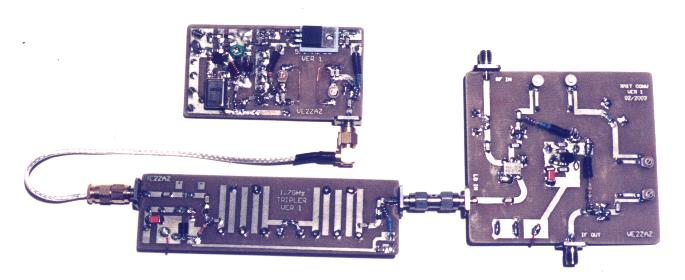
A
1269MHz Transmit Converter with 70cm IF Input
By: Bertrand Zauhar, VE2ZAZ
Published in the
May/June 2003
issue of the Amsat Journal
Page last
updated:
27/02/2005
This
page presents article
"A 1269MHz Transmit Converter with 70cm IF Input" published in the
May/June 2003 issue of the Amsat Journal. This page also provides
updates from the original article.
Here
is the original
article as
I submitted it to Amsat. It is made available to you with the
permission of
Amsat-NA:
Please
visit this page
frequently, and right before assembling the boards, as new information
will get added regularly.
I
would apreciate [
reading back ] from
the ham experimenters who build this project. This will allow me to
improve this page by providing additional clarification if necessary.
Thanks!
Bert,
VE2ZAZ
Since a project like
this lives on, this section offers a list of corrections from the
original Amsat article. As well, any improvements to the original
design will be listed here.
95.3888
MHz Crystal
Equivalent-Model Correction (18/12/2003)
I realize
that I never provided R1, the
Equivalent-Series-Resistance (ESR), to the reader. This may be
requested
by your crystal manufacturer. The value of R1 is "< 50 ohms".
I also noticed that I mis-spelled the
unit
of measure for C1. It is indeed in femto-Farads, not in pico-Farads
like
I stated it in the article. So C1 = 0.60fF. I am pretty sure that
any
crystal manufacturer would have figured out this one anyway.
Both values are now
accurately
shown in table 2 below.
Mixer board amplifier mistake (11/06/2003)
I made an error in
the original published article. On the Mixer board, I should have
listed U2 as an ERA-5 amplifier but it shows an ERA-3 amplifier
instead. Using an ERA-3 will cause excessive compression and the
specified +10dBm of
1269MHz RF output will not be obtainable. Along with making U2 an
ERA-5,
its bias resistor should be replaced with a 43 Ohm. The consequence of
runing two ERA-5 amplifiers on the Mixer board is that the 78L08
voltage
regulator is pushed beyond its 100mA specification. It is then
recommended
to make U1, the voltage regulator, a 7808 instead of a 78L08.
In summary:
- Replace U2 with an ERA-5
amplifier
- Replace R4 with a 43 Ohm
1/2W axial resistor
- Replace U1 with a 7808,
1-Amp voltage regulator
The
shematic and parts table
below were updated to reflect the changes.
Be
careful when
mounting the 7808
on the Mixer board. Notice that pin 1, the input pin, is located on the
left side when reading the marking on the 7808 regulator. This is
reversed compared to the 78L08. The
drawing on the left side illustrates the difference.
|
|
Mixer
board
output power increase
(26/06/2003)
During
testing of different Mixer board
PCB materials, I noted that G10 (FR4) glass-epoxy can have a large
variation in loss tangent depending on the manufacturer, on the batch,
etc. The loss tangent parameter measures how lossy and absorbing a
material can be for a specific frequency. This variation in loss
tangent will have a more noticeable effect as we go up in frequency.
This is especially
true with high-Q microstrip filters such as the ones used on the Mixer
board. As a result, you might notice that RF output power of the
mixer board does not reach the +10dBm specified in the article, despite
sending nominal input level on the IF and LO signals. This would be
caused
by excessive attenuation in the two filters. This effect would have
been
better controlled with the use of higher quality (more exotic and more
expensive)
PCB materials such as Rogers, ceramic, GETek, etc.
An easy
workaround to this effect is to solder a wire between the two
resonating elements of the 1269MHz bandpass filters, as shown in red on
the figure to the right. The wire increases coupling between the
resonating elements, thus decreasing insertion loss of the filter. This
wire has little effect on filter performence for out-of-band rejection.
Use AWG-30 gauge (0.010 inch)
wire such as of the "wire-wrap" type. Run the wire against the PCB
surface
and fit both ends inside the ground vias. Solder to the inside of
vias. A slight touch up on the variable capacitors adjustment may be
required
to peak the output.
Thanks to Jacques VE2AZX for the great idea.
|
|
Tripler
Board -
Capacitor C3 (25/10/2003)
On
the Tripler board, I removed capacitor C3 from the schematic diagram
and
the parts list before publishing, as it was not required. The Amsat
article made no reference to C3 except for component layout figure 5,
which still showed C3 on the left handside portion of the board.
Designation C3 should be left unpopulated on the Tripler board. The board
layout version provided below
has C3
removed. Thanks to Chuck N8LGE for flagging this
to me.
Mixer
board
schematic update to Version 3
(27/10/2003)
Despite
numerous reviews of the
schematics before publishing, the following typo slipped through: The
LO input frequency (left handside of mixer board schematic) should read
1717MHz, not 572.333MHz. The
version of mixer board schematic diagram below is updated.
Thanks
to Jean-Pierre VE2BOS for this
one.
Mixer
Board -
Temporary Testpoint Capacitor
(27/02/2005)
Mike
K9QHO reported to me a mistake
in the Digikey part number I had provided in the parts list below. The
temporary tespoint capacitor on the Mixer board is indeed a 10nF
(.01uF) one. The Digikey number now stands corrected in the table.
|
COMPONENTS
PROVIDED BY FAR CIRCUITS
|
Fred
Reimers from FAR
Circuits is kind enough to provide some of the parts required to
assemble this project. This is done at no additional cost when ordering
the PCB set. All chip capacitors and chip resistors required to
assemble this project are supplied. As well, the 7808 regulators, the
78L08 regulator and the 470nH inductor are provided. This will save you
time and money when assembling the PCBs. Refer to the [ Detailed Parts List ] below for
a detailed list of the components supplied.
Please
visit FAR Circuits
at http://www.farcircuits.net
for more details.
|
ORDERING
FROM
MINI-CIRCUITS LABS
|
I
suggest you order
directly from Mini-Circuits. You will save the distributor's markup.
Visit
their website to find the nearest distribution center. For those
in North America, call the North American Distribution Center to skip
intermediates. There is also an European Distribution Center for those
offshore.
The ERA amplifiers are normally shipped in a minimum strip
size of 10 units. If this represents too much of an expense, you can
request for a smaller shipment. Explain to the sales representative
that
this is for hobby use and that you are not willing to purchase that
many
parts. Insist on getting fewer than 10 units and they will accept your
order like they did with mine.
One final note: Make sure that you request the "drop in" version of ERA
amplifiers, not the surface mount version.
The
circuit schematics were
printed in a reduced size in the article. Here they are in full size.
| The
Mixer board's schematic diagram Version 3 (27/10/2003). |
Click on the figure to
enlarge it.
|
| The
LO board's schematic diagram. |
Click
on the
figure to
enlarge it. |
| The
LO Tripler board's schematic diagram. |
Click on the figure to
enlarge it. |
Similarly,
the PCB layout
drawings are provided here for improved readability.
| The
Mixer board's layout |
Click on the figure to
enlarge it.
|
| The
LO board's layout |
Click on the figure to
enlarge it. |
| The
LO Tripler board's layout Version 2
(25/10/2003) |
Click on the figure to
enlarge it |
|
ADDITIONAL ASSEMBLY
INSTRUCTIONS
|
| Trimcaps
on the Mixer Board
On the Mixer board,
trimcaps should be mounted as shown in the drawing at right.
|
 |
| Trimcaps
on the
LO board
On the 572MHz Lo
board, the three trimcaps should be mounted as shown in the drawing at
right.
|
|
| ERA
Amplifier
Biasing Detail
This is a drawing
that
shows the approach for biasing RF MMIC amplifiers on the LO and Mixer
boards. The LO Tripler board does not require the four ferrite beads,
but the feedpoint principle remains the same.
|
|
| 7808
Voltage
regulator on LO Board
This drawing shows
how
the 7808 voltage regulator should be installed and soldered.
|
 |
Additional
Recommendations
LO
board
- The builder
should solder the external + supply wire before installing U1, the
7808 regulator, as the supply pad is located right under the regulator.
- Y1, the crystal should
have its lead ends shaped in a "L" to allow for better contact with the
PCB pads.
LO tripler board
- If the required +7dBm
output cannot be achieved, the user can reduce the value of
the pi attenuator located between the two inter-digital filters.
Mixer
board
- 75 Ohm chip
resistors are provided by FAR Circuits for R1 and R3 instead of the
specified 78 ohm value. This is an acceptable substitute.
- Diodes D1 and D2 are
optional. They help protect the mixer from an overload at the IF IN
port.
All
three boards
- Inspect the
ERA amplifier areas for any residual copper. The holes should have
no conductive material on their inner wall. As well the triangular
ground pads should not come in contact with the signal traces on either
side.
- The input and output
traces should end flush with the PCB edges. There should not be any gap
without copper between the end of the traces and the PCB edge, as this
would cause an impedance bump. The user can file the PCB edges until
such gap disappears.
- If the builder wishes
to drill holes for mounting the PCB in an enclosure, these holes should
be drilled either in the ground pads or where there are no pads at all.
These holes should be drilled away from coupling elements such
as microstrip filters and wire filters.
- The 4.7uF tantalum
chip capacitors have a line marking that indicates the positive
electrode
The
following tables are
lists of parts with associated Digikey part numbers for reference.
Changes from the original Amsat Journal article are marked in red. Parts
marked with an asterisk (*) are
provided as part of the PCB set.
Table
1: Mixer
Board Parts List (Version 2, 10/06/2003)
| Qty |
Designation |
Description |
Digikey
Part Number |
| 1 |
A1 |
Mini-circuits
ADE-11X mixer. |
N/A |
| 1* |
C1 |
4.7uF,
25V Tantalum |
P11330CT-ND |
| 4 |
C12,
C13, C14, C15 |
1-3pF,
ceramic variable capacitor (trimcap), 0.200” lead spacing.
Sprague-Goodman GKG3R015 or equiv. |
SG3R015-ND |
| 2* |
C2,
C4 |
100nF,
chip 1206 size |
PCC1883CT-ND |
| 10* |
C3,
C5,
C6, C7, C8, C9, C10, C11, C16, C17 |
1000pF,
chip 1206 size |
PCC102BCT-ND |
| 2 |
D1,
D2 |
1N4148
silicon diode |
1N4148MSCT-ND |
| 8 |
FB1–FB8 |
Ferrite
bead. J.W. Miller FB64-110 |
M2305-ND |
| 3 |
J1,
J2,
J3 |
SMA-Female,
PCB mount, gold plated |
ARFX1231-ND |
| 2 |
L1,
L2 |
Leads
form resistors R4 and R8, wound with one-wire spacing, on 1/16” inside
diameter, typically 4 turns are possible. |
N/A |
| 2* |
R1,
R3 |
78
ohms,
chip, 1206 size |
311-78.7FCT-ND |
| 1* |
R2 |
110
Ohms, chip, 1206 size |
311-110FCT-ND |
| 1 |
R4 |
43 Ohms,
axial, 1/2W |
P43BBCT-ND |
| 4 |
R5,
R7,
R9, R11 |
Resistors
not populated. |
N/A |
| 2* |
R6,
R10 |
0
Ohms,
chip, 1206 size. Copper strap 0.1” wide as substitute. |
311-0.0ECT-ND |
| 1 |
R8 |
43
Ohms,
axial, 1/2W |
P43BBCT-ND |
| 1 |
Temporary
testpoint |
1N5711
Schottky diode |
SD101ACT-ND |
| 1 |
Temporary
testpoint |
10nF,
axial or radial |
1103PHCT-ND |
| 1* |
U1 |
LM7808
1-Amp. voltage regulator.
|
MC7808CT-ND
|
| 1 |
U2 |
Mini-circuits ERA-5 MMIC
amplifier, drop-in
type. |
N/A |
| 1 |
U3 |
Mini-circuits
ERA-5 MMIC amplifier, drop-in type. |
N/A |
Table 2: LO Board
Parts List
| Qty |
Designation |
Description |
Digikey Part
Number |
| 1* |
C1 |
4.7uF,
25V Tantalum |
P11330CT-ND |
| 5* |
C11,
C13, C14, C17, C18 |
15pF,
chip 1206 size |
PCC150CCT-ND |
| 2 |
C15,
C16 |
3-10pF,
ceramic variable capacitor (trimcap), 0.200” lead spacing.
Sprague-Goodman GKG10015 or equiv. |
SG10015-ND |
| 6* |
C2,
C3,
C7, C8, C10, C20 |
100nF,
chip 1206 size |
PCC1883CT-ND |
| 6* |
C4,
C5,
C6, C12, C19, C21 |
1000pF,
chip 1206 size |
PCC102BCT-ND |
| 1 |
C9 |
6.5-30pF,
ceramic variable capacitor (trimcap), 0.200” lead spacing.
Sprague-Goodman GKG30015 or equiv. |
SG30015-ND |
| 8 |
FB1-FB8 |
Ferrite
bead. J.W. Miller FB64-110 |
M2305-ND |
| 1 |
J1 |
SMA-F
Female, PCB mount, gold plated |
ARFX1231-ND |
| 2 |
L1,
L2 |
Leads
form resistors R7 and R8, wound with one-wire spacing, on 1/16” inside
diameter. Typically 4 turns are possible. |
N/A |
| 1 |
L3 |
47nH.
3
turns of AWG-22 ( diameter 0.025”) solid enameled copper wire closely
wound on 1/8” inside diameter. |
N/A |
| 1 |
L4 |
120nH.
7
turns, shaped identical to L3. |
N/A |
| 1* |
L5 |
470nH,
axial inductor |
|
| 2 |
L6,
L7 |
1
inch
long of AWG-22 (? 0.025”) solid copper, U-shaped as 1/8”-3/4”-1/8”. |
N/A |
| 1 |
Q1 |
2N3904
NPN transistor, TO-92 case |
2N3904-ND |
| 2* |
R2,
R1 |
4.7
KOhms, chip, 1206 size |
311-4.70FCT-ND |
| 1* |
R3 |
330
Ohms, chip, 1206 size |
311-330FCT-ND |
| 1* |
R5 |
33
Ohms,
chip, 1206 size |
311-33.0FCT-ND |
| 2* |
R6,
R4 |
150
Ohms, chip, 1206 size |
311-150FCT-ND |
| 1 |
R7 |
120
Ohms, axial, 1/2W |
P120BBCT-ND |
| 1 |
R8 |
43
Ohms,
axial, 1/2W |
P43BBCT-ND |
| 1* |
U1 |
LM7808
1-Amp. voltage regulator. |
MC7808CT-ND |
| 1 |
U2 |
Mini-circuits
ERA-3 MMIC amplifier, drop-in type. |
N/A |
| 1 |
U3 |
Mini-circuits
ERA-5 MMIC amplifier, drop-in type. |
N/A |
1
|
Y1
|
95.3888MHz
Crystal, 5th overtone, parallel resonnant, HC-49/U case.
Equivalent-model
characteristics are:
C0 = 5.8pF, C1 =
0.6fF, L =
5.0mH, Q
= 80,000, R1 < 50 Ohms.
|
N/A
|
Table3:
LO Triper Board Parts List
| Qty |
Designation |
Description |
Digikey
Part Number |
| 1* |
C1 |
4.7uF,
25V Tantalum |
P11330CT-ND |
| 2* |
C2,
C4 |
100nF,
chip,
1206
size |
PCC1883CT-ND |
| 8* |
C5,
C6, C7,
C8, C9, C10, C11, C12 |
1000pF,
chip,
1206
size |
PCC102BCT-ND |
| 2 |
J1,
J2 |
SMA-Female,
PCB mount, gold plated |
ARFX1231-ND |
| 2 |
L2,
L1 |
Leads
form
resistors
R1 and R2, wound with one-wire spacing, on 1/16” inside ?. Typically 4
turns are possible. |
N/A |
| 1 |
R1 |
120
Ohms,
axial, 1/2W |
P120BBCT-ND |
| 1 |
R2 |
43
Ohms,
axial, 1/2W |
P43BBCT-ND |
| 2 |
R3,
R5 |
Resistors
not
populated. |
N/A |
| 1* |
R4 |
0
Ohms, chip,
1206
size. Copper strap 0.1” wide as substitute. |
311-0.0ECT-ND |
| 2* |
R6,
R8 |
130
Ohms,
chip, 1206
size |
311-130FCT-ND |
| 1* |
R7 |
47
Ohms, chip,
1206
size |
311-47.0FCT-ND |
| 1* |
U1 |
LM78L08
voltage
regulator, 100mA max |
MC78L08ACPTR-ND |
| 1 |
U2 |
Mini-circuits ERA-3
MMIC amplifier, drop-in type. |
N/A |
| 1 |
U3 |
Mini-circuits ERA-5
MMIC amplifier, drop-in type. |
N/A |
|
